System Architecture
Jupiter Ace system architecture
This page leans into the hardware: CPU, ROM, RAM, memory map, video generation, keyboard, tape I/O, connectors and the quirks that matter for emulation as well as restoration. It is intentionally more detailed than a casual overview because these are exactly the kinds of terms, parts and diagrams that enthusiasts search for.
SYSTEM ARCHITECTURE
Z80A @ 3.25 MHZ
8K ROM · 3K RAM
VIDEO + FONT RAM SPLIT
> MAP MEMORY _
Concept 3 remains the base aesthetic: dark, terminal-led, but roomy enough for reference material.
At a glance
The Ace in one screenful
The Jupiter Ace is a Z80A-based 8-bit machine running at 3.25 MHz with 8 KB of ROM, 3 KB of built-in RAM, 1500-baud cassette storage, a 32 × 24 monochrome display and a 40-key rubber keyboard. The preserved specs also make clear that it exposes two expansion edge connectors and a single-channel buzzer. Unlike the ZX81, it was built around Ace Forth rather than Sinclair BASIC, and unlike the ZX81 it uses dedicated screen and character RAM rather than a ULA-driven video scheme.
CPU
Z80A at 3.25 MHz
ROM / RAM
8 KB ROM, 3 KB base RAM, expansion from 0x4000 upward
Display
32 × 24 characters, 64 × 48 chunky graphics, 128 redefinable characters
I/O
TV out, cassette EAR/MIC, built-in buzzer, main bus edge connector, secondary video connector
Original diagrams
Block-level view of the hardware

What stands out architecturally
- No ULA: contemporary reviews and later hardware reconstructions both point to a board built around the Z80, ROM, SRAM and a large amount of TTL logic rather than a Ferranti-style custom video chip.
- Three 1 KB RAM regions matter most in the stock machine: top working RAM, screen RAM and character generator RAM.
- The video system is character-based, but the character generator itself is RAM, so the machine can redefine all 128 glyphs and fake more graphical behaviour than a static ROM font would allow.
- The smaller rear connector is unusually useful because it exposes video-related signals, which is why third-party colour-board projects could latch onto the Ace without replacing the whole machine.
No definitive original Jupiter Cantab schematic appears to survive online in official form; the preservation scene instead relies heavily on reverse-engineered or redrawn schematics published later.
Memory
Why the Ace memory map is worth a deep dive
The Ace's headline "3 KB RAM" figure hides a much more interesting arrangement. The preserved manual and memory-map documentation show 8 KB of ROM at 0x0000–0x1FFF, then a partially decoded 0x2000–0x3FFF region where video RAM, character RAM and working RAM appear in mirrored forms. That matters to anyone writing low-level code, debugging hardware, or emulating the machine accurately.

Key addresses
Important ranges at a glance
| Range | What lives there |
|---|---|
| 0x0000–0x1FFF | 8 KB ROM: Ace Forth kernel, editor, built-in words and support routines. |
| 0x2000–0x23FF | Screen RAM, one access view of the visible 32 × 24 display map. |
| 0x2400–0x27FF | Mirror of screen RAM with different practical CPU/video behaviour. |
| 0x2800–0x2BFF | Character generator RAM, holding redefinable glyph shapes. |
| 0x2C00–0x2FFF | Mirror of character RAM, again useful for understanding fetch/write quirks. |
| 0x3C00–0x3FFF | Top 1 KB working RAM: system variables, dictionary, data stack and return stack. |
| 0x4000+ | External expansion RAM, where 16 KB and 48 KB packs extend the machine. |
The exact mirrored-access behaviour matters most for low-level software, restoration work and faithful emulation, which is why it is worth surfacing explicitly rather than hiding it in prose.
ROM first, language first
The machine boots straight into Forth because the ROM is not just a monitor; it is the operating environment, editor and built-in word set.
Display and glyph RAM
The Ace gives real RAM to both the screen map and the font, which is why it can redefine all 128 characters and fake richer graphics than its monochrome display suggests.
Forth workspace
This upper block is the machine's real working heart: system variables, dictionary growth, safety gap, data stack and return stack all converge here.
Where the Ace starts to breathe
Once expansion RAM appears, the Ace becomes far more practical for larger Forth projects, utilities and more ambitious software than the stock 3 KB suggests.
Key memory behaviours
- ROM: the first 8 KB contains the Forth kernel, editor, built-in words and support code.
- Video RAM mirror pair: 0x2000–0x23FF and 0x2400–0x27FF refer to the same underlying screen RAM, but the manual and ROM notes distinguish CPU-priority and video-priority access behaviour depending on which range is used.
- Character RAM mirror pair: 0x2800–0x2BFF mirrors 0x2C00–0x2FFF, again with differing practical behaviour because the video logic fetches glyph rows while the CPU writes definitions.
- Top working RAM: the last 1 KB, normally used at 0x3C00–0x3FFF, holds system variables, the dictionary link into user-defined words, the data stack and the return stack.
- Expansion: extra RAM begins at 0x4000, which is why 16 KB and 48 KB packs feel natural on the Ace.
Component deep dive
Major subsystems and what they do
CPU and ROM
The preserved general specifications describe a Z80A at 3.25 MHz paired with 2 × 4 KB EPROMs. Period bench tests also describe the ROM as 8 KB and the board as carrying the processor, speaker and ROM chips on the rear portion of the single main PCB.
From a software point of view, the most important consequence is that the Ace boots directly into Forth, not into a BASIC interpreter pretending to be an operating system. The ROM therefore doubles as firmware, language environment and command interface.
Working RAM, dictionary and stacks
The final 1 KB of the internal RAM is not merely "program space". The manual and ROM listing show it split between system variables, the user dictionary, a 12-byte safety gap, the upward-growing data stack and the downward-growing return stack. This layout is very Forth-flavoured and explains why memory upgrades are so valuable once programs become serious.
Screen RAM
The screen is a 24 × 32 character display, so only 768 bytes are needed for the visible screen map. The hardware colour-board article describes 1 KB of RAM storing one byte per character location, with the remainder of the block used by the system as workspace. The review literature also emphasises that this is a proper memory-mapped screen.
Character generator RAM
The Ace's most distinctive hardware trick is that the font is held in RAM rather than ROM. Seven bits from the screen byte select one of 128 character shapes, while three extra address lines pick one of the eight scanlines that make up that character row. Because the character definitions live in RAM, every character can be redefined by the user.
Video logic
The colour-board article is especially useful here because it lays out the video path in plain terms: address counters feed the screen RAM, screen bytes address the character RAM, the selected dot row is loaded into a shift register, and the serialised bitstream becomes raw video before blanking and sync are added. Contemporary reviews confirm that the Ace uses discrete TTL rather than a custom ULA for this work.
Keyboard and sound
The published specs and reviews consistently describe a 40-key rubber keyboard with auto-repeat. Sound is a simple internal speaker or buzzer, CPU-driven rather than handled by a dedicated sound chip. The BEEP word expects pitch and duration values, which reinforces that the firmware is exposing hardware control directly through Forth words.
Buses, connectors and expansion
Why the Ace is more open than it first looks
Main edge connector
The general specs and bench tests both describe a main expansion edge carrying power, address, data and control lines from the CPU. That makes the Ace unusually attractive for RAM packs, printer interfaces and other bolt-on logic because so much of the machine bus is already available at the back.
Secondary video connector
Jupiter's second rear connector is more obscure but arguably more interesting. The colour-board project states that it carries video RAM address, data and write-enable lines plus the composite video signal path. That is how later colour add-ons could track the screen and generate per-character attributes.
Tape and file handling
Mass storage is a domestic cassette recorder at 1500 baud. The 1982 review notes that SAVE, LOAD and VERIFY are built in, that SAVE writes the whole dictionary in RAM to tape, and that a leader tone is written to let the recorder settle before the data begins. This is one of the most practical hardware-facing facts for emulator design because .TAP support maps neatly to the original workflow.
RAM packs and growth
The memory-map documentation states that additional RAM starts at 0x4000, with 16 KB and 48 KB expansions producing totals often described as 19 KB and 51 KB systems once the built-in 3 KB is included. Reviews from the period and the modern hardware scene both make clear that these upgrades were central to the Ace's usefulness.
Emulator relevance
Implementation notes and visual reference
Rather than pushing these into a narrow right-hand rail, this section keeps the practical emulator notes and reference material full-width and easier to scan.
Details worth modelling accurately
- Mirrored RAM regions
- CPU/video priority differences by address
- Write-only behaviour of character RAM
- 1500-baud cassette load/save flow
- BEEP pitch and duration behaviour
- Dictionary, data stack and return stack layout in top RAM
Photo reference
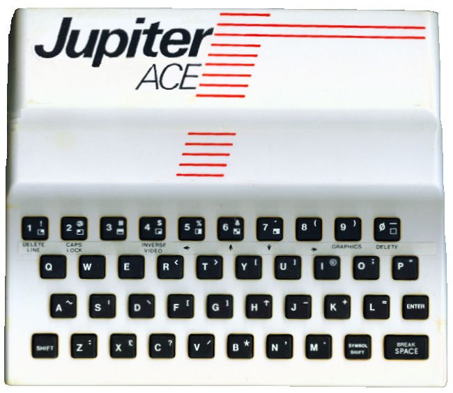
Public domain image: “Jupiter-ace-issue-1.jpg”, via Wikimedia Commons.
Sources and attribution
Primary references used for this page
- What is a Jupiter Ace? — general specs including CPU, ROM/RAM, display, tape and connectors.
- Jupiter Ace Memory Map and ROM listing — memory ranges, mirrors and internal layout.
- Jupiter Ace manual — detailed description of how memory is laid out.
- Hardware Colour Board Project — the clearest public description of the Ace video chain and the secondary video connector.
- Personal Computer World bench test and Electronics & Computing review — period descriptions of the board, keyboard, screen, speaker and tape behaviour.
- Build your own Jupiter Ace and later reconstruction notes — useful for chip-level reconstruction of the original memory parts.
Page map